
 |
 |
 |
| Assembly | Computer | Bus |
 |
 |
 |
| Devices | Drivetrain | Chassis Mk1 and Mk2 |
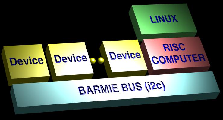
How do you make a modular robot? Well, instead of putting all sorts of sensors and actuators on your general IO pins, you create a bus. With a bus, you do not waste IO space. You add as many devices to your robot as you like: you only spend a mere bus address per device, instead of valuable IO pins which are a finite resource on every computer.
An added benefit of a bus, is it's topology: the bus-topology. This means that you can have a module hook up to the bus, at a location that is convenient for you. Consider the coax 10Base2 versus UTP 10BaseT. If you add a computer to your 10Base2 network, you can hook up at the nearest coax section. On the 10BaseT, you are forced to hook up at a predefined location: the location of the hub or switch. So it comes down to this: star-topology is bad (lots of wiring req'd). bus-topology is a good thing.
I decided to use the I2C bus protocol for Barmie's bus. And of course, I also put the power on the bus, so all devices get both power and communications from the bus. The physical implementation is done using 6 pins 1mm flat flex cables with ZIF connectors. I created the backbone of the bus by scraping off the coating of a flex cable at several places, and soldering SMD connectors on it. This is tricky stuff, and requires quite some soldering skills. Do not attempt this without a small tipped soldering iron. The pin layout for the bus was chosen like this:
      SDA
      SCL
      GND
      GND
      +3.3V
      +5V
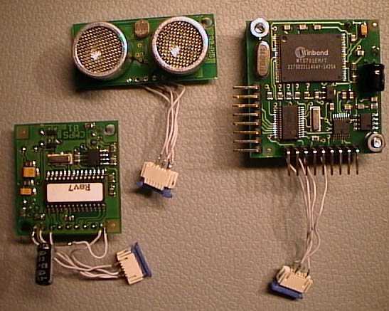
So, what devices are hooked up then?
Well, I get my robot parts from
Robot Electronics.
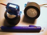
In the picture at the top of this page, we have: SRF08 sonar, CMPS01 compass and SP03 speech synthesizer.
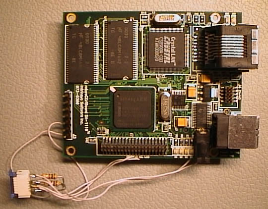
Barmie's heart comprises a powerfull 192MHz StrongArm risc computer, called the CerfCube. On the picture below, you can see the computer with its bus connector. The connector has been fitted with bus terminators. For all devices, only 2 general purpose IO pins were used: SDA and SCL signals for the i2c bus.
Programming this robot is a very comfortable process. No need to muck around with micro controllers or assembly. Barmie can be programmed in any language available for linux. In my case, I use C++ with STL using a cross compiler over NFS. I find this pretty amazing, as robotics used to be considered too low level for a high level construct like STL. Barmie has plenty of diskspace, and if I need to expand, I simply put a gigabyte of compact flash or so in its CF slot.
To give you an idea of the elegance with which I program Barmie, consider the actual code snippet. (I created classes for compass, speech and sonar, which all derive from I2CDevice, which has a reference to I2CBus as a member var). bus. Also very cool: Scan() actually returns a list of addresses of i2c devices that have been detected run-time on the bus.
#include "i2cbus.h"
#include "speech.h"
#include "sonar.h"
#include "compass.h"

int main()
{
  I2CBus bus(0);
  bus.Scan();

  Compass compass(bus);
  Speech speech(bus);
  Sonar sonar0(bus,0xe2);
  int rng1 = sonar0.Range();
  char text[80];
  sprintf(text,"range is %d centee meters", rng1);
  speech.Speak(text);
  speech.WaitWhileSpeaking();
}
| camera | c0 |
| compass | c0 |
| servo | c2 |
| Speech | c4 |
| Sonar0 | e2 |
| Sonar1 | e4 |
I think I've created a very nice linux device driver.
It uses two interrupts, one for vsync, one for hsync.
The vsync interrupt is enabled when the user reads an image.
After the first vsync interrupt, the hsync interrupt is enabled
as well. Both are disabled upon the completion of the frame.
Known bug: upon network load, some pixels are lost.
This is very bad, because the G/B and G/R sequencing is lost,
so that for the remaining scanline, G/R or G/B is reversed.
Also, the device driver does QCIF only, and relies on userspace
prog to configure the omnivision chip via i2c first. But that's
OK with me.
May 2003
I am suffering from a lot of noise on the syncing lines.
If one of the bus wires is in proximity of a syncing wire,
I will get a lot of spurious interrupts on the sync signal.
The syncing works OK when the databus is unconnected.
When the databus is connected, the syncing is messed up.
I tried larger diameter wires and shorter wires for the
sync signals. This did not help. Maybe add a spike filter?
Feb 2003
Jan 2003
Jan 2003
Dec 2002
Builder's Log
Jun 2003
Yeah! the camera works. Here's the evidence:
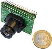
Purchased this C3088 digital camera.
I interfaced this using the LCD port LDD0-LDD7, and using
GPIO5,GPIO7,GPIO8 for the PCLK, HREF and VSYNC signals.
Unfortunately, it is not yet working correctly, as you can see
in this image, which was created using polling code, whereas
I should use interrupts.: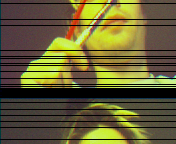
Barmie has been assembled and now features
speech,
sonar,
differential drive,
tilt/pan head,
compass.
It has two ethernet interfaces, one 10baseT wired ethernet,
and one IEEE 802.11b wireless ethernet device (compact flash) from
conceptronic.
The wireless ethernet is currently used in Ad-Hoc mode with my laptop.
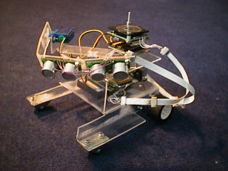
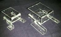
Formed a chassis by heating and bending acryl sheets.
In the picture on the top, you can see Mk1, the small one.
This is not a chassis out of a single sheet. I glued two
small sections on the main chassis for the front wheels.
Mk1 had to go, because with the Conceptronic Wireless CF card
installed, the strongarm board would not fit. Mk1 is a very
small and very cute chassis. Mk2 on the other had is much larger,
and less cute.
I bought a Conceptronic C11CF Wireless card for my CerfBoard.
With some help of the cerfcube yahoo group, I now have it working
in Ad-hoc mode.
This means I can transfer data from my laptop to my robot at a
staggering rate. I measured a 1000 Kbyte/sec with an ftp session.
Added a SD20 servo controller to the system.
Works just fine now, after finding a short in my circuit.
Unfortunately, the servos cannot be set back to an idle mode
without a pulse train.
Also, I modified two Hitec HS-55 miniature servos, to act as my drive train.
It was modified by replacing the potentiometer with two 2k2 Ohm resistors.
On one, I accidentally dislodged an SMD component on the back side while
soldering the resistors. This caused erratic servo movement.
I am considering to drive tracks or treads instead of wheels with these
servos. For the moment, I've created this very compact drivetrain, with a set of
FischerTechnik wheels.
TODO
![]()